
Oostende Radio Callsigns "OST & OSU"
September 2006
Text & Pictures © Michel Bougard,
Pre retired Radio Officer, GMDSS GOC,
Aircraft ROC
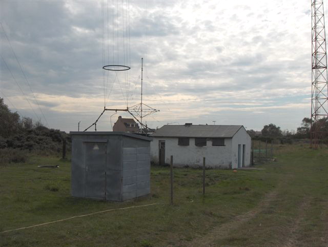
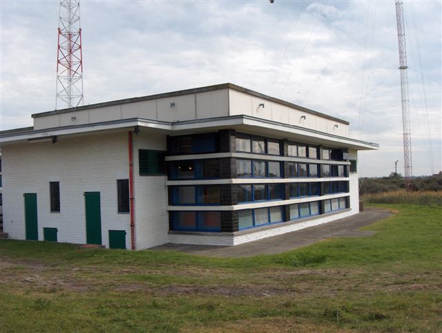
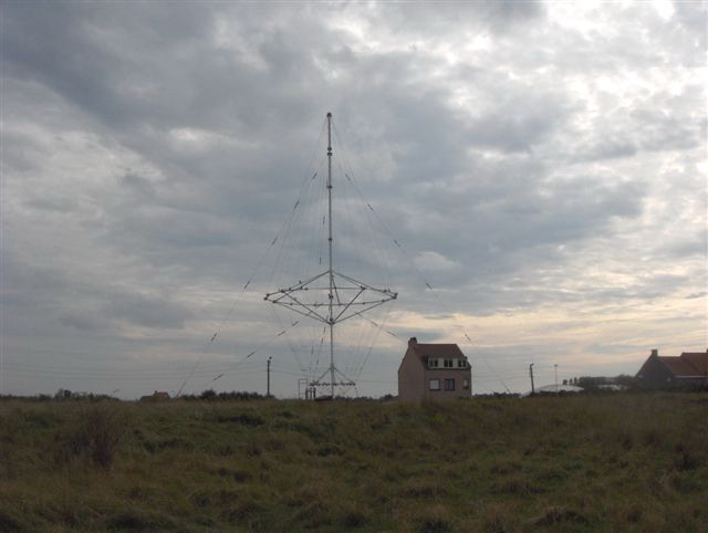
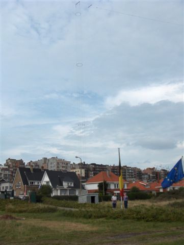
Antenna TG1 room of the transmitter Z60 for NAVTEX 518 kHz.
The white building is the old cloakroom of the soccer club "Goldstar", now the chicken room of the Middelkerke sending station caretaker .
Beyond, the Reuse 1 antenna of the Z10 transmitter on medium and short wave (1,8 - 28 MHz).
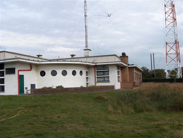
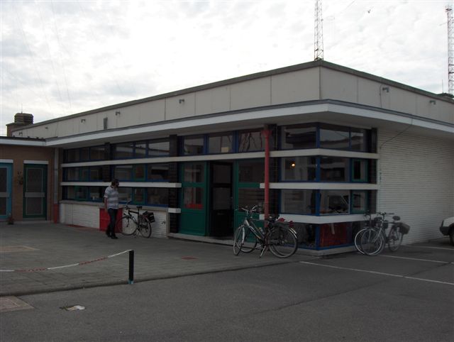
Main building of the sending station in
Middelkerke (3)
Middelkerke (3)
The new part out of red brick on the right on the photograph is the house of the caretaker of the sending station.
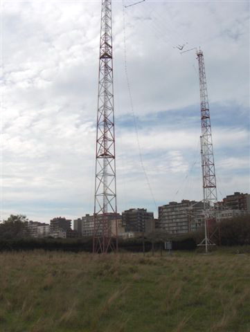
Reuse 1 antenna of the Z10 transmitter for medium and short wave (1,8 - 28 MHz) of the sending station in Middelkerke.
Beyond, a house of the “Duinenweg” (the road of the dunes) and the top of the white inflatable hall of the communal tennis club.
Antenna Reuse 2 of the Z11 transmitter and masts 3, 4 and 5 of the antenna dipole of the Z15 transmitter of the sending station in Middelkerke
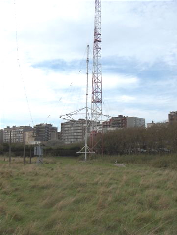
Antenna Reuse 2 of the Z11 transmitter of the sending station in Middelkerke.
Dipole antenna room and the 4 and 5 masts of 55 m high of the transmitter Z15 (1,5 - 9 MHz) of the sending station in Middelkerke.
Beyond, the Reuse 2 antenna of the Z11 transmitter on medium and short wave (3,5 - 28 MHz)
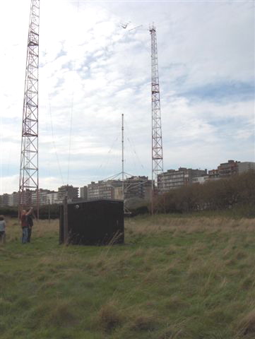
The access path to the sending station "Dr. Hector Verhaeghelaan" in Middelkerke , and in the center, the cabin of the cage 2 antenna for medium waves (1,6 - 2,8 MHz) between the 6 and 7 masts along this avenue.
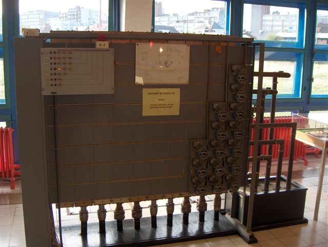
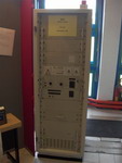
Matrix antenna switch of the sending station in Middelkerke. .
In this photograph, bellow of the switch, the arrival of the antennas cables.
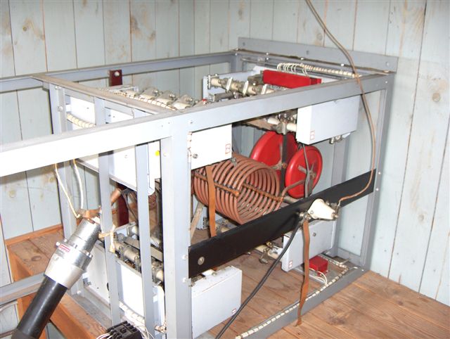
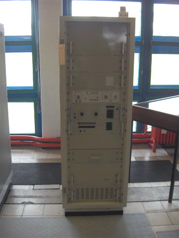
Tuning circuit for the medium waves (1,6 - 2,8 MHz) in the room of the antenna cage 2 of the sending station in Middelkerke.
The tuning circuit is similar to the tuning circuits of the linear amplifiers of the transmitters aboard ships.
The circuit is primarily made up of coils brown and condensers in red.
The black cable in bottom on the left is the connection to the transmitter in the main building.
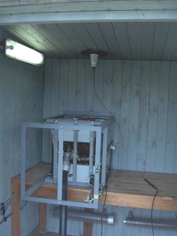
Antenna tuning circuit “Philips Telecommunications” of the cage 2 antenna room of the sending station in Middelkerke.
The goal of this antenna tuning circuit is to use the cage 2 antenna for the intermediate frequencies (1,6 - 2,8 MHz), therefore to increase the wavelength of the antenna.
To notice under the tuning circuit, the electric heating resistances.
That points out to certain ships !
Click HERE to return to front page
Click HERE to go to the next page of images